 Loading... Please wait...
-
Call us on (559) 432-8873
- My Account
- Items / $0.00
All prices are in All prices are in USD
Categories
ARRL QST Product Review - "M2 6M-1K2 High-Power 6 Meter Amplifier"
Posted by Jeff Klein, K1TEO on 12th Nov 2015
Republished with permission from November 2015 QST ARRL,
the national association for Amateur Radio® www.arrl.org
Reviewed by Jeff Klein, K1TEO
About 5 years ago, M2 Antenna Systems introduced a high power solid state amplifier for 6 meters (model 6M-1000) capable of a full kilowatt of output. It was lightweight and small, making it usable both at home and for portable operations. Later they came out with a higher power 2 meter solid state amplifier called the 2M-1K2. I had a chance to review that amplifier and came away with a favorable opinion.4 Now there is a 6 meter version that is similar to the 2 meter version in look and capabilities the 6M-1K2. It is capable of delivering up to 1250 W of output, uses a 50 V dc supply that can be purchased integrated with the amplifier or added on separately, and like its predecessor is relatively lightweight and small.
Overview
The M2 6M-1K2 is a compact amplifier, measuring just 6 × 7.125 × 13.4 inches (height, width, depth) when set up without the optional internal power supply. When configured this way, it weighs 13 pounds. When the optional 2400 W switching power supply is integrated, the package grows to 9 inches tall and weighs 20.5 pounds. This makes it easy to use for DXpeditions or portable operation. We opted for the amplifier/power supply package for this review. In my station, it takes up about the same room as a desktop transceiver.
The amplifier uses a single Freescale LDMOSFET, an MRFE6VP61K25H, to generate power. The device can be driven to full output with about 5 W. Because most of us have transceivers that run significantly more power, M2 has set the amplifier to be driven with 50 – 100 W of input by using a built-in attenuator to achieve the correct drive level.
To run the optional internal power supply, a 240 V connection with a 15 A maximum is required. If you want to use a different supply, it will need to provide 48 – 50 V dc at about 40 A.
Front Panel

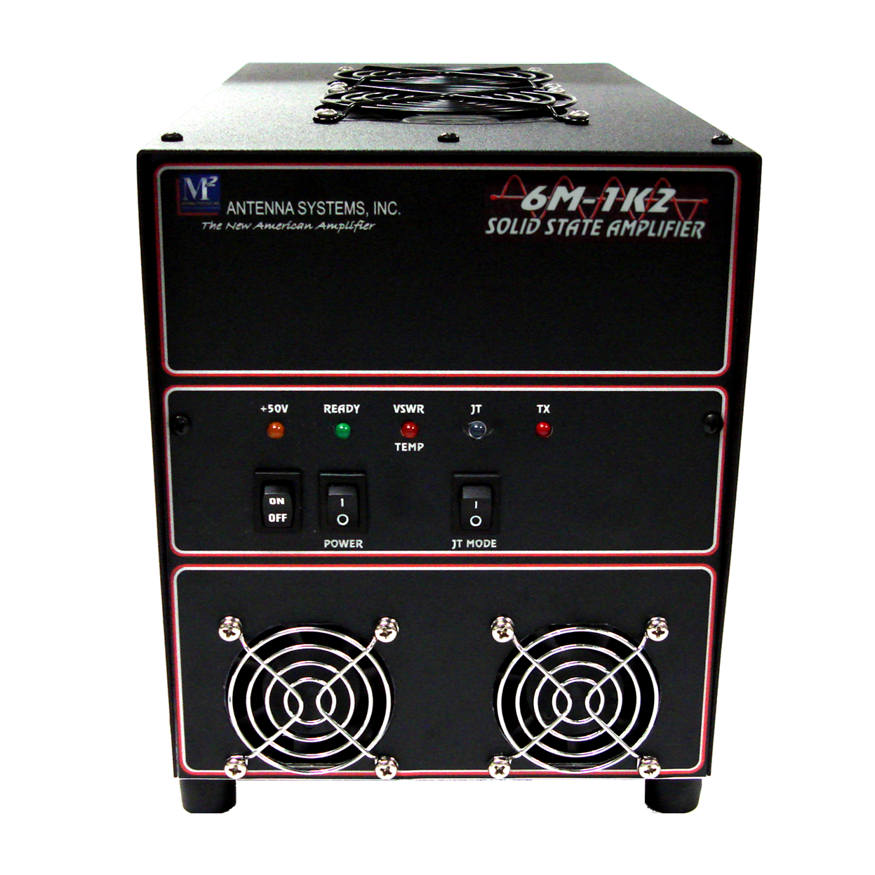
The front of the amplifier has three switches and five lights that allow the operator to monitor and manage the status. The POWER switch controls the integrated power supply and turns on the 50 V dc. The amplifier can also be placed in or out of line using the READY switch.
The final switch on the front panel is to place the mode in or out of “JT mode.” JT is shorthand for WSJT, the software commonly used for weak signal digital communications. In JT mode, the amplifier runs closer to Class C, operating cooler and more efficiently for high duty cycle modes such as WSJT and FM that don’t require linear amplification. In JT mode, the rated output drops slightly as the drain current drops from the about 36 A to about 30 A.
The amplifier is protected from both high SWR and overheating. If the SWR is greater than 2.5:1 at the output, the amplifier will shut down and the VSWR/TEMP LED on the front panel will illuminate. If this condition occurs, you can recycle the amplifier quickly by toggling the READY switch to reset the amplifier.
If the amplifier overheats, the same VSWR/TEMP LED will come on to indicate the fault. The instructions say that this condition is “very rare” and if it does occur you should let the amplifier cool for 30 minutes before trying to operate. My operating included several high-intensity periods where the amplifier was used at maximum power with continuous SSB or CW transmissions for up to 2 hours. I was curious to see how hot the amplifier got. The amplifier has two fans on the lower front panel to cool the internal power supply and two on top above the heat sink on the RF section. Though a little noisy (more on this later), they worked effectively to keep the amplifier cool. Even after lengthy usage the heat sink, accessible from the back of the unit, was no more than warm. My experience seems to confirm that under normal operating an overheating situation should be unusual.
Rear Panel Connections

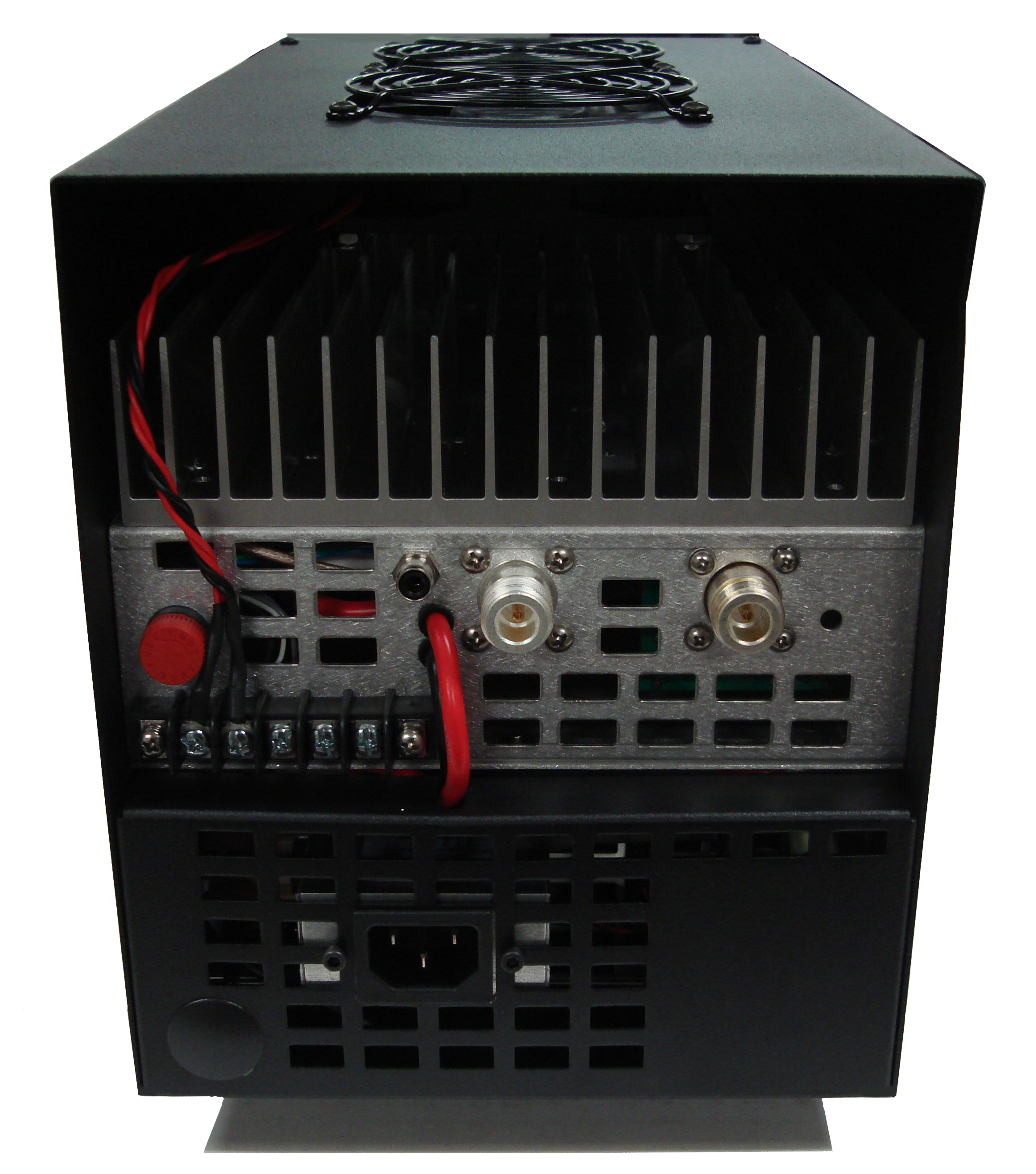
The rear of the unit has two chassis mounted N female connectors for the RF input and the RF output. As I noted in my earlier review of the M2 2 meter amplifier, neither connector is marked, though they are clearly shown in the instructions.
Keying the 6M-1K2 requires a path to ground through a phono jack on the rear of the unit. Keying the amplifier throws the built-in input and output relays. This is done with a built in 15 – 20 millisecond delay (per the instructions; ARRL Lab testing showed the delay to be 12 ms) to be sure the relays are closed before bias voltage is applied to the gates of the LDMOS device. This is a nice feature to help protect external preamps. In my case, I used my receive preamplifier without a sequencer and this delay did work to protect my preamplifier. I’ve damaged it in the past when I’ve used it without a sequencer with other amplifiers.
The other major connection on the back panel is for an external ac power cord when the amplifier includes the built-in power supply. Otherwise there are #10 AWG power leads to hook up an external 50 V supply.
There is also a terminal strip with a number of connections. Two of the screw terminals, connected at the factory, supply 28 V dc to the top cover fan. There is also a connection point for an external relay key return if the operator is keying external components. Another connection point supplies +13.6 V dc at 500 mA, convenient for hooking up external relays and preamps. In my case I didn’t have a need to use any of these connections but they are nice features to have available.
A fuse is also accessible from the rear panel. It protects the internal regulator and components.
Documentation
The M2 6M-1K2 includes a 19-page printed manual that covers installation, a review of the features, and troubleshooting. It also includes a helpful overview of the theory of operation as well as block diagrams of the amplifier’s components and one showing a typical installation. To assist with troubleshooting there is a full schematic of the RF section and another of the control board. For those not familiar with WSJT, there is an addendum that provides information about the mode, use of the software, and references on how to obtain the software
online.
The instructions are clearly written and should provide the information needed to get the amplifier on the air and help the user understand all of the available features.
Setup
Getting the 6M-1K2 on the air took just a few minutes. Since the test unit came with the built-in power supply, it was merely a matter of plugging in the ac cable that came with the amplifier to provide 240 V. As I already use an external amplifier on 6 meters, the next step was to move the coax from the transceiver to the M2 amplifier and likewise move the amplifier output coax over as well. I key my current amplifier in the same way as the M2 amplifier (ground to transmit) so once the RCA jack was connected I was basically good to go. That was the extent of the setup simple and fast!
If you’re not currently using a high power amplifier on 6 meters, be sure that anything connected to the output has an adequate power rating at this frequency. Coaxial jumpers, feed lines, wattmeters, antennas, and so on all need to be able to handle 1200 W or more.

Using the Amplifier
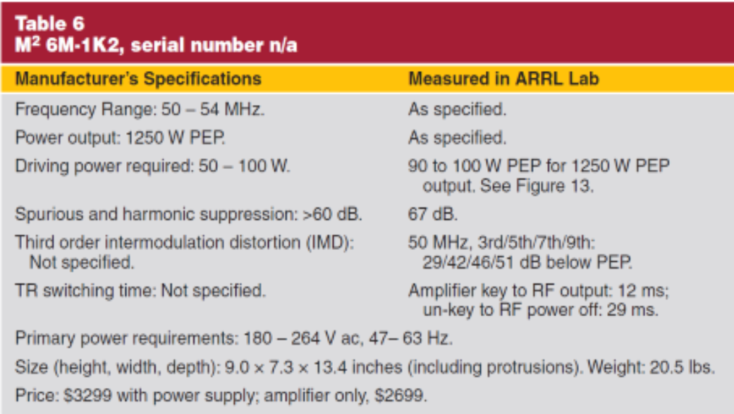
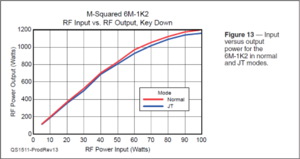
I drove the amplifier with my Kenwood TS-2000 transceiver which has a digital power indicator. I found that at about 80–85 W input from the transceiver I could achieve the maximum amplifier output as measured in my shack with a Bird wattmeter. I did not notice any significant difference on SSB or CW. The same was true when using WSJT with the amplifier in JT mode. Testing in the ARRL Lab (see Table 6 and Figure 13) showed that 90 – 100 W is needed for full output. It also shows that the amplifier output is only modestly different when running with JT mode switched on. I have used several high-power solid state amplifiers and continue to enjoy the instant on (no warm-up period) aspect. This amplifier is no exception once the POWER and READY switches are thrown the amplifier is ready to use.
Once you turn the amplifier on, you will hear the lower fans come on immediately. They do so with some significant noise and then quickly drop to a lower level. However, during transmit, the fans speed up again to increase cooling, and the fans on the top of the amplifier come on as needed. In JT mode, the fan comes on as soon as the
amplifier is keyed.
Operation
I had a chance to put the 6M-1K2 through its paces in several contests, including the Spring 6 Meter Sprint contest, the ARRL June VHF Contest, and the CQWW VHF Contest in July. I kept the amplifier at or near full power output in each event, and it performed flawlessly. Over-the-air reports were just what users would want inline or out, my signal quality was the same. With its significant cooling capabilities, the amplifier was never more than slightly warm, even after extended periods of WSJT and CW operating.

If there was one minor concern, it was the amount of fan noise the amplifier generated. When transmitting, the fans tended to race and, though not loud, it was a bit distracting when I operated without headphones. I situated the amplifier on top of my existing 6 meter tube amplifier, close to my operating position and at about head height. That was convenient to allow me to easily use the existing input and output cables as well as the PTT line. That had some impact on the noise generated. If I was using this amplifier on an ongoing basis I would probably locate it farther away because there are no meters to monitor. As long as I have a power output meter in line and viewable, I can confirm the amplifier is working. Of course, it probably shouldn’t be too far away if you want to switch to WSJT mode conveniently when desired. The amplifier switches to JT mode automatically after 5 seconds of continuous duty operation.
Final Thoughts
Overall, I would give the M2 6M-1K2 high marks for its performance. It delivered the power level as expected. Very importantly, it had a clean signal, something critical when operating with nearby stations at this power level. It was about as easy a setup as you would hope to have with a high-power amplifier. On top of that, it would have been very easy to take this setup portable. As with the 2 meter version, I came away with a highly favorable impression of this amplifier and think it would make a valuable addition for any serious 6 meter operator.
Manufacturer:
M2 Antenna Systems
4402 N Selland Ave
Fresno, CA 93722
tel 559-432-8873
Click <HERE> for PDF version of this article
Republished with permission from November 2015 QST ARRL,
the national association for Amateur Radio® www.arrl.org
